Wednesday, October 12, 2011

Retaining wall clasification after the used material

            Using the material as criteria for a clasification we have the following retaining wall types:

  • Lumber retaining wall,type of wall that can be also: 
  1. anchored :-very popular due to instalation ease and lower material cost
-can be easily manufactured using recycled timber from an old structure framing
     -is commenly used in lanscape areas
      -the required length and spacing both vertical and horizontal of the anchors are calculated  based upon the wall height,lateral earth pressure and surcharge loading
     -the anchors("deadmen") are attached to the face timbers by spices and/or drift pins

    2. crib-wall: -very similar to the anchored lumber retaining wall in terms of ease and lower   material cost and technique  of assembly( members attached together by means of spikes and/or  drift pins);
    -better suited for areas where adequate space is not available or where the imposed  loads  are expected to be greater.
    - is constructed as an interconnected box with all sections working together to support   the intended loads. 
    -also commonly used in landscaped areas.
    3.wall-post and lagging-made of wooden posts and wooden laggings;
    -the posts can be installed with  a footing depth depending of the nature of the soil(even without a footing);
    - specially suitable when space and time (very fast construction needed) constraints are present;
    - can be also used as a wind barrier .

    -an example of a study case calculation for such a structure can be accesed here !
    •  Steel retaining wall,such as:
    1.cantilever sheet pile:-where STEEL SHEETS are used as vertical members embedded into the ground     to  resist lateral soil pressure through cantilever action;
      -usually used to retain noncoeziv soils as sand and gravel.

    2.steel soldier pile with concrete or lumber  lagging:-build with vertical I-SECTION STEEL POSTS  embedded  into the ground at regular spacings and horizontal CONCRETE/LUMBER LAGGINGS are placed between the steel plange members to retain soil.
    3.anchored steel sheet pile-where STEEL SHEETS are used as vertical members embedded into the ground     to  resist lateral soil pressure through cantilever action,but they are also pinned using cables or other stays wich are anchored into the rock or the soil behind it.
    4.anchored steel soldier pile-similar to the anchored steel sheet pile but insted of the steel sheets are used soldier pile. 
    • Concrete retaining wall such as:
    1.cantilever-constructed of reinforced concrete and it supports backfill soil by a cantilever action;
    -the cantilevered stem portion is fixed at the bottom and is free at the top;
    -the base slab serves as a fixed support and prevents against sliding and overturning;
    -there is an option to install a key at the bottom of the base slab to ensure further safety against sliding;
    -these walls provide prolonged durability and serviceability;
    -they are widely used due to their ease in construction and cost-effectiveness.

    - for an in depth analysis on how to proper design such a wall click here or here ! 
    2.gravity:
    -is constructed using mass concrete placement and generally without reinforcement,but sometimes with a slight  reinforcement placed where the concrete is porred in different stages;
    -the support of backfill and other imposed loads on these walls is provided by the sheer weight of the unit,is wide at the base and it tapers towards the top;
    -the overturning moment acting on this type of wall is counter-balanced by the resisting moment on account of the self-weight of the wall.
    3.crib-wall:
     - is an assemblage of individual concrete members of particular standard sizes,is generally used for lower backfill heights, in areas where horizontal space is limited, and where foundation excavations are more difficult( can be constructed at multiple heights along any cross-section)
    -the strong interlocking feature between individual crib members provides good stability to the overall structure;
    -the positive drainage of water from the backfill material through the gaps between members alleviates the need for a separate drainage system,but the minimum construction time, cost-effectiveness and less embedment depth make this type of wall popular for many different applications.
    4.butressed-(reinforced/unreinforced):
    -is a special type of Cantilever Retaining Wall with additional support in the form of buttress which are perpendicular to the retaining wall and are monolithic with the structure;
    -is usually used  against heavy lateral loads,it  can support a greater height of backfill;
    -depending on the height of the backfill and possibility of surcharge and/or possible seismic activities some reinforcement can be added to increase  its structural strength.
    • Masonry retaining wall such as:
    1.reinforced cantilever:
     -this type of retaining wall assembly mainly consists of standard masonry blocks reinforced with steel and a core of concrete;
    -these walls are similar to concrete cantilever retaining walls in shape and also behave in much the same manner.
    -for a in depth presentation on how to proper design such a wall please follow this link 

    2.mass block segmental gravity retaining wall:
    -is constructed from interlocking, dry-stacked (without mortar), precast block elements of standard shapes and dimensions, which are arranged in a running bond configuration;
    -it  resist destabilizing forces due to retained soils solely through the self-weight and embedment of the block elements so there for this wall is used for relatively low-height walls.
    3.mass block retaining wall reinforced-
    -this type of retaining wall consists of precast block elements of standard shapes and dimensions with interior holes which act as keys ensures bondage between the elements and give stability to the whole wall system;
    -this wall also has provisions for reinforcement in the form of small precast holes through which steel rods can be inserted.

    -for a in depth analysis on how  to proper design such a structure click here !
    • Special retaining wall structure:
    -TERRACED RETAINING WALL-CONCRETE
    -TERRACED RETAINING WALL-MASONRY
    -TERRACED RETAINING WALL-LUMBER-
    - TERRACED RETAINING WALL-STEEL


    Calculation Steps

    -->        

               Before begining to design a retaining wall we need to establish the different restraints that we might have in terms of :
    • site geometry and initial conditions ;
    • the nature of soil(soft, rock or different layers);
    • the posibility of  using as much site material as possible;
    • for slopes with heights above 1.5m  we need to determine the depth of the water behind the future retaining wall in order to determine the hydrostatic pressure
    • nature of soil in front and at the base of the future retaining wall .

      Saturday, October 8, 2011

      Cantilever retaining wall

                                 
                     Cantilever Retaining  Wall- is made from an internal stem of steel-reinforced, cast-in-place concrete or mortared masonry (often in the shape of an inverted T).
      These walls cantilever loads (like a beam) to a large, structural footing, converting horizontal pressures from behind the wall to vertical pressures on the ground below. Sometimes the cantilever retaining  wall is butressed on the front, or include a counterfort on the back, to improve the strength resisting high loads.
      Buttresses are short wing walls at right angles to the main trend of the wall. These walls require rigid concrete footings below seasonal frost depth. This type of wall uses much less material than a traditional gravity wall.
      These rigid concrete footings must be positioned into firm suitable foundations.The wall operates like a beam — cantilevering the load to a large, fixed structural base — converting horizontal pressures from behind the wall into vertical pressures onto the ground below.Sometimes cantilevered walls are buttressed(include short wing-like walls at right angles to the main trend of the wall) on the front, or include a counterfeit on the back, to improve their stability against heavy loads.
      A free design aplication that we strongly recommend to properly design a cantilever retaining wall is:
      •  iCADonline-a free web based cantilever retaining wall analysis software that enables you to check :
      1. sliding and
      2. overturning,
      3. bearing capacity  control for: static and dynamic analysis case-that can be used by clicking here
      or for more advanced design and calculation you can use the free :
      • GEO5-a free demo version of GEO5 software wich is a very complete program that includes the Cantilever aplication that is used by most professionals in geotechnical engineering and that you can be downloaded by clicking here .

      Main features of GEO5:

      -Verification analysis can be performed employing EN 1997-1, LRFD or classical approach (limit states, factor of safety)
      -EN 1997 – option to choose partial factors based on National Annexes
      -EN 1997 – option to choose all design approaches, consider design situations
      -Analysis of internal stability (overturning, translation, load-bearing capacity of foundation soil)
      -Verification of concrete cross-sections according to various standards (EC2, BS 8110, IS456, CSN, PN)
      -Analysis according to the theory of limit states and safety factor
      -Generally layered soil environment
      -Built-in database of soil parameters
      -Arbitrary number of surcharges applied to structures (strip, trapezoidal, concentrated load)
      -Arbitrary number of inserted forces (anchors, safety fences, etc.)
      -Modelling of water in front of and behind structures, modelling of artesian water
      -Possibility to not consider pressure in the front
      -General shape of terrain behind the structure
      -Berms in front of the structure
      -Various types of pressures in front of the structure (at rest, passive, reduced passive)


        Anchored retaining wall

                                   
                     Anchored wall-is a  wall that is usually pinned both top and bottom using cables, or other stays, which are anchored in the rock or soil behind it.Anchors are driven into the material and then expanded at the end of the cable, either by mechanical means or by injecting pressurised concrete into the hole. The concrete expands to form a bulb in the soil.
        The anchor wall may be embedded at the base and tied to a slab at the top or to a “deadman anchor” — a concrete structure which is driven into the ground or anchored to the earth with sufficient resistance. The horizontal cable, rod or helical anchor, and deadman structure resists forces that would otherwise cause the wall to become unstable.This method, though technically complex, is useful where high loads are expected, or where the wall itself has to be slender and would be too weak without anchoring.


             For this type of wall we recommend the same programs as for the piling walls  for they are the most suited for this subject and because anchored walls  are sugested when the piling walls  will not fit the both desired partial and global stability safety factors,and they are:
        • Prosheet- a free comprehensive  software  for Cantilever and Anchored Sheet Wall Systems according to the Blum theory. The ProSheet 2.2 defines all the forces required for determing a sheet piling structure.
        The results produced by this method have to be checked carefully by the user in order to make sure that modelization of the soil-structure interaction is accurate enough (e.g. arching effects leading to higher anchor forces and lower bending moments in the wall).
           For the design of the head wall three static systems are possible:

        - cantilever
        - free earth support with one layer of anchor or struts
        - fixed earth support with one layer of anchor or struts.


        The anchor wall may be free-earth or fixed-earth supported.

        The following loads are taken into consideration for the head wall as well as for the anchor wall:
        - earth pressure behind the wall
        - earth pressure in front of the wall

        - water pressure behind the wall

        - water pressure in front of the wall


        - uniform infinite surcharges on the soil surface (Caquot) 

        - concentrated linear surcharges (max 5) at any location (Boussinesq)

        - point forces at any location of the wall (Concentrated Forces)

        - a pressure diagram on the back of the wall.


        The program defines the design characteristics based on the input data given by the user and the results are printed out in graphical as well as tabular form.
        The design can be made in either metric or imperial units-you can download the sofware by clicking here .

        • SLOPE/W-from GEO-SLOPE a comprehensive program that you can download for free only a trial version and you can view a sheet pile wall design example by clicking -here (a specific case study for such a wall after EC7 can be viewed here !
        • GEO5-Sheeting Design-program  used to design sheet pile structures,it provides required pile embedment lengths (for fixed and hinged toes), pile bending moments, internal forces and anchor loads program that can be downloaded by clicking here .

        Main features of the GEO5-Sheeting Design:

        -Analysis according to the theory of limit states and safety factor
        -Generally layered soil environment
        -Verification analysis can be performed employing EN 1997-1, LRFD or classical approach (limit states, factor of safety)
        -EN 1997 – option to choose partial factors based on National Annexes
        -EN 1997 – option to choose all design approaches, consider design situations
        -Built-in database of soil parameters
        -Arbitrary number of surcharges applied to structures (strip, trapezoidal, concentrated load)
        -Modelling of water in front of and behind structures, modelling of artesian water
        -General shape of terrain behind the structure
        -Earthquake effects (Mononobe-Okabe, Arrango)
        -Analysis of earth pressures in effective and total parameters
        -Multiple levels of struts
        -Application of specified forces and moments
        -Analysis of soldier beams
        -Verification of external stability of a wall using program Slope Stability .


          Friday, October 7, 2011

          Sheet pile wall


          Piling walls- are usually used in soft soils and tight spaces. A sheet pile wall is made out of steel, vinyl or wood planks which are driven into the ground. For a quick estimate the material is usually driven 1/3 above ground, 2/3 below ground, but this may be altered depending on the environment. A taller sheet pile wall will need a tie-back anchor, or "dead-man" placed in the soil a distance behind the face of the wall, that is tied to the wall, usually by a cable or a rod. Anchors are placed behind the potential failure plane in the soil.


                     There are a lot of softwares that can usually asses the type of sheet pile wall you need to use in order to design a good retaining wall,we recommend the following:

          • Prosheet- a free comprehensive  software  for Cantilever and Anchored Sheet Wall Systems according to the Blum theory. The ProSheet 2.2 defines all the forces required for determing a sheet piling structure.
          The results produced by this method have to be checked carefully by the user in order to make sure that modelization of the soil-structure interaction is accurate enough (e.g. arching effects leading to higher anchor forces and lower bending moments in the wall).
               For the design of the head wall three static systems are possible:

            - cantilever
            - free earth support with one layer of anchor or struts
            - fixed earth support with one layer of anchor or struts.


            The anchor wall may be free-earth or fixed-earth supported.


            The following loads are taken into consideration for the head wall as well as for the anchor wall:

            - earth pressure behind the wall

            - earth pressure in front of the wall

            - water pressure behind the wall

            - water pressure in front of the wall


            - uniform infinite surcharges on the soil surface (Caquot) 

            - concentrated linear surcharges (max 5) at any location (Boussinesq)

            - point forces at any location of the wall (Concentrated Forces)
            - a pressure diagram on the back of the wall.

            The program defines the design characteristics based on the input data given by the user and the results are printed out in graphical as well as tabular form.
            The design can be made in either metric or imperial units-you can download the sofware by clicking here .

            • SLOPE/W-from GEO-SLOPE a comprehensive program that you can download for free only a trial version and you can view a sheet pile wall design example by clicking -here

            Wednesday, October 5, 2011

            Gravity Wall Design


            Gravity Wall


            Construction types of gravity retaining walls
            A gravity wall depends on the weight of their mass (stone, concrete or other heavy material) to resist pressures from behind and will often have a slight 'batter' setback, to improve stability by leaning back into the retained soil. For short landscaping wall, it is often made from mortarless stone or segmental concrete units (masonry units). Dry-stacked gravity walls are somewhat flexible and do not require a rigid footing in frost areas. Home owners who build larger gravity walls that do require a rigid concrete footing can make use of the services of a professional excavator, which will make digging a trench for the base of the gravity wall much easier.

            Earlier in the 20th century, taller retaining walls were often a gravity wall was made from large masses of concrete or stone. Today, taller retaining walls are increasingly built as composite gravity walls such as: 
            • geosynthetic and with precast facing;
                                                            
            •  gabions (stacked steel wire baskets filled with rocks); 


            • crib walls (cells built up log cabin style from precast concrete or timber and filled with soil);


            •  or soil-nailed walls (soil reinforced in place with steel and concrete rods).

              For an advanced design we recommend first studying  a hand calculation that you can download by clicking - here ,and then downloading the GEO5-demo version that inludes the Gravity Retaining Wall Modul,download page that you can access by clicking - here .


                Saturday, October 1, 2011

                Terms explanation

                               When designing a retaining wall we need to evaluate and understand  the following terms:


                • cohesive strength(c) -of the retained material wich can be explained as the interior own strength(shear     strength)of a  material besides his own weight;
                • unit weight(y)-of a material wich is defined as the weight per unit volume of a material;
                • angle of  friction((φ-phi)-wich is the maximum angle of a certain material that will remain stable and will not begin sliding.
                      Also in order to proper design a retaining wall we need to take in consideration the following earth pressures categories:
                • active earth pressure
                • passive earth pressure
                • earth pressure at rest
                 In addition it is possible to account for the following effects having on the earth pressure magnitude:
                • influence of loading
                • influence of water pressure
                • influence of broken terrain
                • friction between soil and back of structure
                • wall adhesion
                • influence of earth wedge at cantilever jumps
                • influence of earthquake
                When specifying rocks it is also necessary to input both the cohesion of rock c and the angle of internal friction of rock (φ). These values can be obtained either from the geological survey or from the table of recommended values. 


                 Recommended values for typical calculations:
                           Soil Type                        Ø(φ , °)      γ(KN/m3)                c(kPa) 
                                Gravel                               30                20                          0 
                                 Sand                                20                20                          0 
                                 Clay                                 15               19                          10 
                           Concrete                                30               24                          200 
                  Armed concrete                              45               25                          400 
                 Geocelular protection                       20               18                           10


                  • Active and passive pressure

                  The active state occurs when a soil mass is allowed to relax or move outward to the point of reaching the limiting strength of the soil; that is, he soil is at the failure condition in extension. Thus it is the minimum lateral soil pressure that may be exerted. Conversely, the passive state occurs when a soil mass is externally forced to the limiting strength (that is, failure) of the soil in compression. It is the maximum lateral soil pressure that may be exerted. Thus active and passive pressures define the minimum and maximum possible pressures respectively that may be exerted in a horizontal plane.

                  • Rankine theory

                  Rankine's theory, developed in 1857, is a stress field solution that predicts active and passive earth pressure. It assumes that the soil is cohesionless, the wall is frictionless, the soil-wall interface is vertical, the failure surface on which the soil moves is planar, and the resultant force is angled parallel to the backfill surface. The equations for active and passive lateral earth pressure coefficients are given below. Note that φ' is the angle of shearing resistance of the soil and the backfill is inclined at angle β to the horizontal:
                   K_a = \cos\beta \frac{\cos \beta - \left(\cos ^2 \beta - \cos ^2 \phi \right)^{1/2}}{\cos \beta + \left(\cos ^2 \beta - \cos ^2 \phi \right)^{1/2}}  ; Ka=active coeficient for earth type 
                   K_p = \cos\beta \frac{\cos \beta + \left(\cos ^2 \beta - \cos ^2 \phi \right)^{1/2}}{\cos \beta - \left(\cos ^2 \beta - \cos ^2 \phi \right)^{1/2}} 
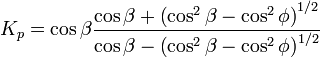
;  Kp=passive coeficient for earth type
                  For the case where β is 0, the above equations simplify to
                   K_a = \tan ^2 \left( 45 - \frac{\phi}{2} \right) \
                   K_p = \tan ^2 \left( 45 + \frac{\phi}{2} \right) \


                  • Coulomb theory

                  Coulomb (1776)  first studied the problem of lateral earth pressures on retaining structures. He used limit equilibrium theory, which considers the failing soil block as a free body in order to determine the limiting horizontal earth pressure. The limiting horizontal pressures at failure in extension or compression are used to determine the Ka and Kp respectively. Since the problem is indeterminate, a number of potential failure surfaces must be analysed to identify the critical failure surface (i.e. the surface that produces the maximum or minimum thrust on the wall). Mayniel (1908) later extended Coulomb's equations to account for wall friction, symbolized by δ. Müller-Breslau (1906) further generalized Mayniel's equations for a non-horizontal backfill and a non-vertical soil-wall interface (represented by angle θ from the vertical).
                   K_a = \frac{ \cos ^2 \left( \phi - \theta \right)}{\cos ^2 \theta \cos \left( \delta + \theta \right) \left( 1 + \sqrt{ \frac{ \sin \left( \delta + \phi \right) \sin \left( \phi - \beta \right)}{\cos \left( \delta + \theta \right) \cos \left( \beta - \theta \right)}} \ \right) ^2}


                   K_p = \frac{ \cos ^2 \left( \phi + \theta \right)}{\cos ^2 \theta \cos \left( \delta - \theta \right) \left( 1 - \sqrt{ \frac{ \sin \left( \delta + \phi \right) \sin \left( \phi + \beta \right)}{\cos \left( \delta - \theta \right) \cos \left( \beta - \theta \right)}} \ \right) ^2}
                  For an in-depth analysis on how to proper estimate your geotechnical in site conditions click here ! For an automated calculation of active,passive and at-rest pressures you can try a free application that you can acces by clicking   here .
                                            

                  Retaining wall design-Definition & types

                                         Definition: a retaining wall is a structures built in order to hold back earth which would otherwise move downwards. The purpose of a retainin wall  is to stabilize slopes and provide useful areas at different elevations (e.g. terraces for agriculture, buildings, roads and railways).

                                 The most important consideration in proper design and installation of retaining walls is to recognize and counteract the fact that the retained material is attempting to move forward and downslope due to gravity. This creates lateral earth pressure behind the wall which depends on the angle of internal friction (phi) and the cohesive strength (c) of the retained material, as well as the direction and magnitude of movement the retaining structure undergoes.
                                    Lateral earth pressures are zero at the top of the wall and - in homogenous ground - increase proportionally to a maximum value at the lowest depth. Earth pressures will push the wall forward or overturn it if not properly addressed. Also, any groundwater behind the wall that is not dissipated by a drainage system causes hydrostatic pressure on the wall. The total pressure or thrust may be assumed to act at one-third from the lowest depth for lengthwise stretches of uniform height.
                  Unless the wall is designed to retain water, it is important to have proper drainage behind the wall in order to limit the pressure to the wall's design value. Drainage materials will reduce or eliminate the hydrostatic pressure and improve the stability of the material behind the wall. Drystone retaining walls are normally self-draining.
                            A proper  retaining wall design to ensures stability against overturning, sliding, excessive foundation pressure and water uplift, critereas that are insured  by designing them  for a minimum safety factor in static conditions of:
                  • 1.3 against lateral sliding and  
                  • 1.5 for overturning;
                  and a minimum safety factor in sesimic conditions of:
                    • 1.1 against lateral sliding
                    • 1.3 for overturning.
                                   Every retaining wall supports a “wedge” of soil. The wedge is defined as the soil which extends beyond the failure plane of the soil type present at the wall site, and can be calculated once the soil friction angle is known. As the setback of the wall increases, the size of the sliding wedge is reduced. This reduction lowers the pressure on the retaining wall.The basement wall is thus one form of retaining wall.However, the term is most often used to refer to a cantilever retaining wall, which is a freestanding structure without lateral support at its top.Typically retaining walls are cantilevered from a footing extending up beyond the grade on one side and retaining a higher level grade on the opposite side. The walls must resist the lateral pressures generated by loose soils or, in some cases, water pressures.
                                       Retaining wall types:

                    For an advanced study on choosing the proper retaining wall solution for a specific case study you can check out the following pdf !

                    Popular Posts